Reading and Plotting UTM Coordinates with MapTools Tools
These tools let you read and plot UTM Coordinates on a paper map with more precision than the printed grid lines alone allow. Each printed grid line is labeled with its Easting or Northing in meters; a plotting tool adds the distance from the nearest grid line to your feature. Add the two together and you have a full UTM coordinate. The five form-factors below — grid style tool, slot style tool, corner ruler roamer, mini corner style tool, and map ruler — all do the same job in slightly different ways. The grid style tool reads to 100m precision; the other four reach 10m precision on a 1:24,000 map. Before using any of them, confirm your map's scale matches the tool's scale and that you know which UTM zone you are working in. Most USGS topo maps print a UTM grid at 1,000m spacing, though 10,000m and 100m grids also exist. Always read the Easting first, then the Northing.
A complete UTM coordinate
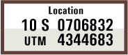
A complete UTM coordinate has three parts: a zone designator, an Easting in meters, and a Northing in meters — for example, Zone 10S, 706832mE, 4344683mN. The zone comes from the map's marginalia. The Easting and Northing — with all their digits — come from the printed grid labels plus the additional precision your plotting tool resolves. On a GPS receiver set to display position in UTM, the same three components appear:
Reading and plotting
All five tools work in either direction. The procedures below walk through the read direction — start with a feature on the map, end with its coordinates. Plotting (start with coordinates, end with a mark on the map) is the same procedure run in reverse:
- To read: measure the Easting and Northing offsets from the western and southern grid lines, then add each offset to the corresponding grid-line label to get the full coordinate.
- To plot: subtract the grid-line labels from the target Easting and Northing to get the offsets you need, position the tool so those offsets land on the grid lines, then mark where the tool indicates the target — at its corner, in its slot, or at the right tic on its scale, depending on which tool you're using.
The Corner Ruler Roamer section spells the plot direction out explicitly; the other tools work the same way in reverse.
The worked example
The five sections that follow all use the same illustrated point — the same Zone 10S, 706832mE, 4344683mN as the GPS display above — so you can compare how each tool truncates the reading to its native precision. In every case the feature sits in the 1km grid square bounded on the west by 706000mE and on the south by 4344000mN; the precise offset of the feature within that square is 832m east and 683m north.
UTM Grid Style Tool
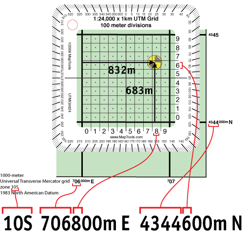
A grid style tool is a transparent square ruled into a fine grid — 100m divisions for a 1:24,000-scale tool — that you align with the printed UTM grid lines and read the offset directly off its own scales. For many land-navigation situations, 100m precision is plenty.
- Identify the grid line just west of your feature and the grid line just south of it, and read their Easting and Northing values from the map's grid labels. In the illustration the western grid line is
706000mEand the southern grid line is4344000mN. - Place the tool over the grid so its edges line up with those two printed grid lines.
- Read the Easting offset along the tool's bottom edge — the number of 100m divisions east of the western grid line to your feature. In the illustration the feature sits between the
8and9marks; truncated to 100m, the offset is800m E. - Read the Northing offset along the tool's left edge the same way. The feature sits between the
6and7marks, so the offset truncates to600m N. - Add each offset to its grid-line value:
Zone 10S, 706800mE, 4344600mN—706000 + 800east of zone 10's central meridian,4344000 + 600north of the equator.
UTM Slot Style Tool
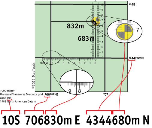
A slot style tool has a horizontal base ruler that sits along the southern grid line and a vertical slot — with a fine-divisioned north-south ruler — that slides east and west to bracket the target. On a 1:24,000-scale tool, both rulers give you 10m precision.
- Position the base of the tool on the southern grid line of the square containing your feature. In the illustration that's
4344000mN. - Slide the tool east–west until the target is centered in the vertical slot.
- Read the Easting value of the western grid line from the map's grid labels —
706000mEin the illustration. - Read the Easting offset where the base ruler crosses the western grid line. The feature's offset truncates to
830m E, giving a full Easting of706830mE. - Read the Northing offset where the vertical ruler in the slot crosses the target. The offset truncates to
680m N, giving a full Northing of4344680mN. - The feature is at
Zone 10S, 706830mE, 4344680mN.
UTM Corner Ruler Roamer
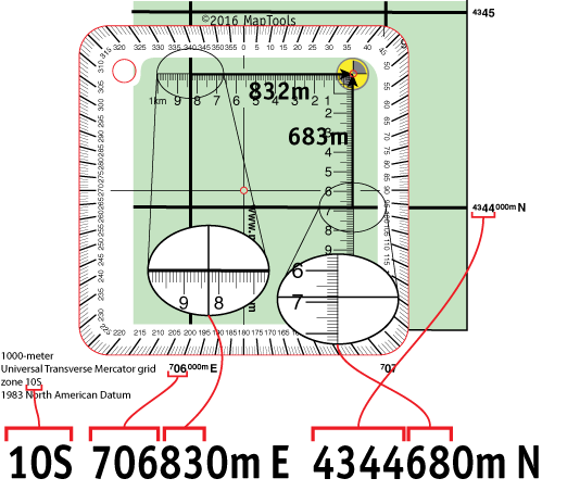
A corner ruler roamer is a baseplate-style tool (with a compass-rose protractor on most models) carrying a UTM corner ruler. The corner sits on your feature, with two perpendicular rulers extending west and south — far enough to cross the western and southern grid lines of the square. At a 1:24,000 scale it reads to 10m precision.
- To read a feature's coordinates, place the corner of the ruler exactly on the feature, with the two ruler edges extending west and south.
- Read the Easting value of the western grid line from the map (
706000mEin the illustration). Read the Easting offset where the west-extending ruler crosses that grid line —830m Ein the illustration. - Read the Northing value of the southern grid line (
4344000mN). Read the Northing offset where the south-extending ruler crosses that grid line —680m N. - Add each offset to its grid-line value:
Zone 10S, 706830mE, 4344680mN. - To plot a known coordinate, position the corner so the offsets you want line up with the grid lines, then mark the map at the corner.
- If the grid square sits on the edge of your map and there is no room to the west or south, start from a different corner. The method still works — just remember that UTM values increase from west to east and from south to north.
Field expedient: if you are on an odd-scaled map or left your tools behind, you can build a quick corner ruler from a scrap of paper. Use the map's metric scale bar to mark off one kilometer and the 100m subdivisions along one edge, repeat along the other edge of the corner, and number both scales starting from zero at the corner.
UTM Mini Corner Style Tool
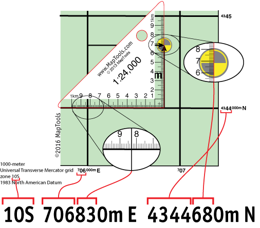
A mini corner style tool is a compact triangular ruler — same operating principle as the corner ruler roamer, smaller and lighter. The right-angle corner sits on the feature with the two scale edges extending west and south. On a 1:24,000-scale tool, 10m precision.
- Place the right-angle corner exactly on the feature, with one ruler edge extending west to (or past) the western grid line and the other extending south to the southern grid line.
- Read the Easting offset where the west-extending edge crosses the western grid line —
830m Ein the illustration. The full Easting is706000 + 830 = 706830mE. - Read the Northing offset where the south-extending edge crosses the southern grid line —
680m N. The full Northing is4344000 + 680 = 4344680mN. - The feature is at
Zone 10S, 706830mE, 4344680mN.
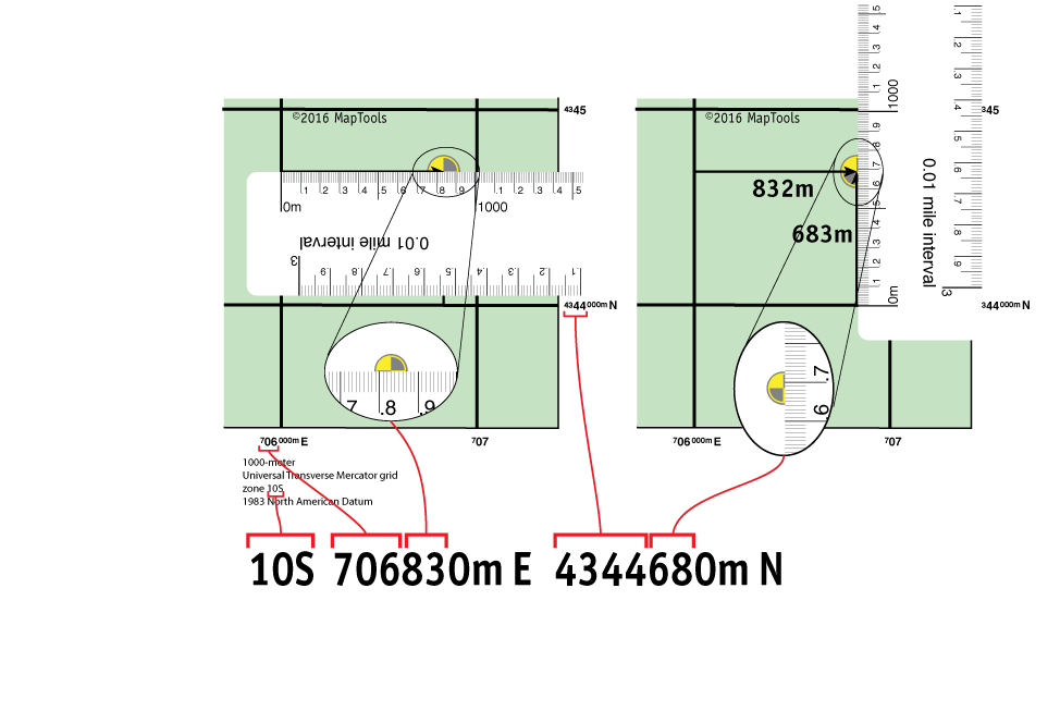
UTM Map Ruler
A map ruler is a straightedge marked with a metric distance scale — 10m tic intervals on a 1:24,000-scale ruler. There is nothing UTM-specific about it at all: you are simply measuring two distances in meters, which is exactly what a UTM Easting and Northing are. Use the ruler twice per coordinate — once for the Easting, once for the Northing — at 10m precision on a 1:24,000 map.
- For the Easting, lay the ruler horizontally inside the grid square at the feature's north-south position, with the
0mmark on the western grid line and the scale extending east. Read where the feature falls on the scale —830m Ein the illustration. Add to the western grid line:706000 + 830 = 706830mE. - For the Northing, lay the ruler vertically inside the grid square at the feature's east-west position, with the
0mmark on the southern grid line and the scale extending north. Read where the feature falls —680m Nin the illustration. Add to the southern grid line:4344000 + 680 = 4344680mN. - The feature is at
Zone 10S, 706830mE, 4344680mN.
Further reading on maptools.com
All five tool styles are made for several different map scales. The original step-by-step tutorials and additional background are on maptools.com:
- Quick guide to UTM coordinates: https://maptools.com/tutorials/utm/quick_guide
- Grid overlay tutorial: https://maptools.com/tutorials/utm/grid_tools
- Corner ruler tutorial: https://maptools.com/tutorials/utm/corner_tools
- Slot tool tutorial: https://maptools.com/tutorials/utm/slot_tools